d-Cube, DC1
Specifications
| Article number | DC1 |
|---|---|
| Dimensions | 120 mm x 120 mm x 40 mm |
| Weight | 290 g (without connectors), 310g (with P1-A, P1-B and power supply connector) |
| Temperature range | -40 - 85 °C |
| Electrical | |
|---|---|
| Power supply | 8-40 Vdc |
| Maximum power consumption | 1.8 W |
Description
The purpose of d-cube is to collect data from the target equipment, which is typically a PLC, a SCADA/HMI, a local database, a building automation system, a yacht, a truck or any device exposing data via supported protocols.
It connects typically either via RS-485, or via RS-232, or via Controller Area Network or via Ethernet ports.
d-cube is designed to be easy to install and trouble shoot.
The following data sources are currently supported:
-
Modbus (both RTU an TCP) master (requires an available slave)
-
Modbus (both RTU an TCP) sniffer (it passively reads data from an existing communication between a master and a slave)
-
OPC-UA (beta)
-
NMEA 0183 (beta)
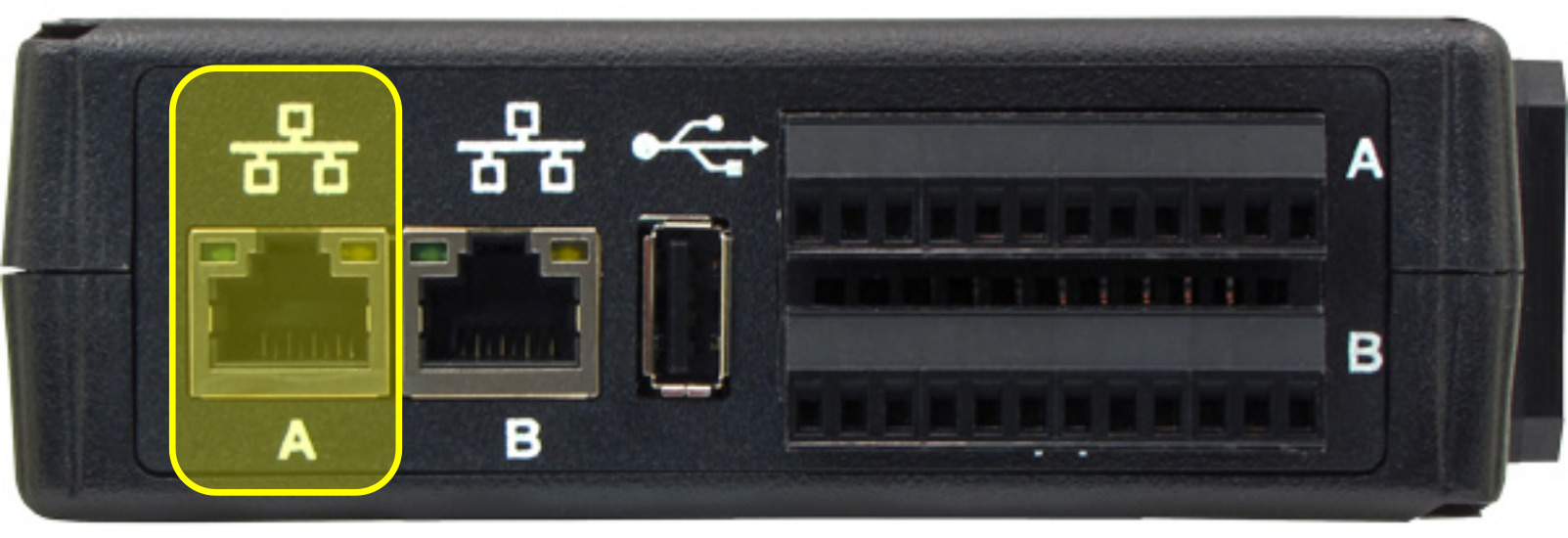
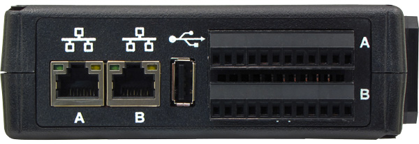
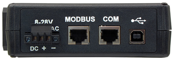
d-cube looks like this:
Interfaces
RS-232
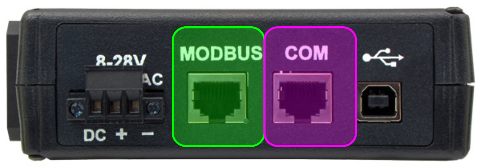
There are 2 RS-232 ports: COM1 and COM4.
COM1 and COM4
They are both located at COM RJ-45 connector:
Pinout as follows:
| Pin | Name |
|---|---|
| 1 | NO CONNECT |
| 2 | NO CONNECT |
| 3 | GND |
| 4 | GND |
| 5 | COM1-RS-232-RXD |
| 6 | COM1-RS-232-TXD |
| 7 | COM4-RS-232-RXD |
| 8 | COM4-RS-232-TXD |
RS-485
There are 2 RS-485 ports: COM2 and COM3.
COM2
Is located at MODBUS RJ-45 connector:
Pinout as follows:
| Pin | Name |
|---|---|
| 1 | GND |
| 2 | GND |
| 3 | GND |
| 4 | COM2-RS-485-A+ |
| 5 | COM2-RS-485-B- |
| 6 | NO CONNECT |
| 7 | NO CONNECT |
| 8 | GND |
COM2 is terminated with a 120\(\Omega\) resistor.
COM3
Is located at SCREW TERMINAL, P1-A 12 pin connector:
Pinout as follows:
| Pin | Name |
|---|---|
| 1 | GND |
| 2 | COM3-RS-485-A+ |
| 3 | COM3-RS-485-A- |
| 4 | NO CONNECT |
| 5 | NO CONNECT |
| 6 | NO CONNECT |
| 7 | NO CONNECT |
| 8 | NO CONNECT |
| 9 | NO CONNECT |
| 10 | NO CONNECT |
| 11 | NO CONNECT |
| 12 | NO CONNECT |
COM3 is has a jumper selectable 120\(\Omega\) termination.
CAN bus
There are 2 CAN ports: CAN0 and CAN1.
CAN0
Is located at SCREW TERMINAL, P1-B 12 pin connector:
Pinout as follows:
| Pin | Name |
|---|---|
| 1 | GND |
| 2 | NO CONNECT |
| 3 | NO CONNECT |
| 4 | NO CONNECT |
| 5 | NO CONNECT |
| 6 | CAN0-CAN_L |
| 7 | CAN0-CAN_H |
| 8 | NO CONNECT |
| 9 | NO CONNECT |
| 10 | NO CONNECT |
| 11 | NO CONNECT |
| 12 | NO CONNECT |
CAN0 is has a jumper selectable 120\(\Omega\) termination.
CAN1
Is located at COM RJ-45 connector:
Pinout as follows:
| Pin | Name |
|---|---|
| 1 | CAN1-CAN_H |
| 2 | CAN1-CAN_L |
| 3 | GND |
| 4 | GND |
| 5 | NO CONNECT |
| 6 | NO CONNECT |
| 7 | NO CONNECT |
| 8 | NO CONNECT |
CAN1 is terminated with a 120\(\Omega\) resistor.
Installation
d-cube installation is super easy and you can make it your-self.
The installation requires a power supply for d-cube, at least 1 cable to connect to target equipment and 1 cable to connect to Internet.
You need to run these steps: mounting, connect to target equipment and connect to Internet.
Mounting
- mount d-cube utilizing the available DIN Rail plug
- connect the power supply

- check power-up
- enable power supply
- wait 120 seconds boot process (after about 90 seconds the read LED will blink for approximately 5 seconds)
- power-off
- disable power supply
Connect to target equipment
d-cube can connect to multiple targets at the same time. Each target might require a specific cable.
- power-off
- disable power supply
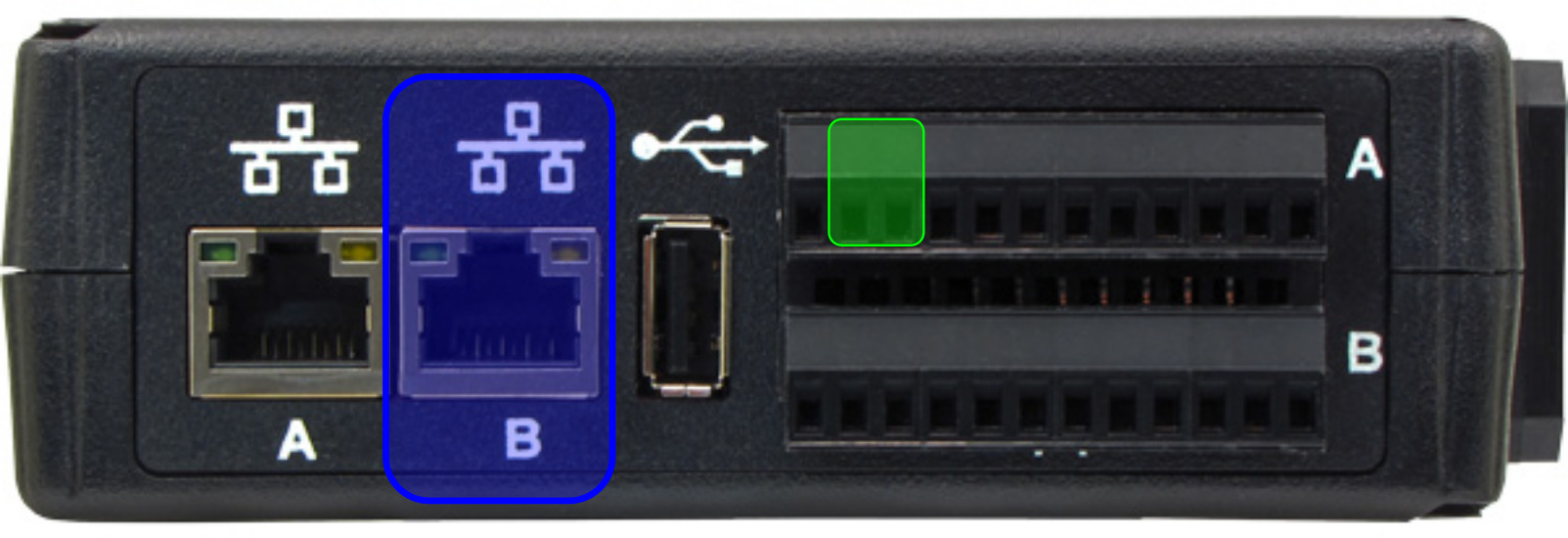
- connect each needed d-cube port to the target equipment
- power-up
- enable power supply
- wait 120 seconds boot process (after about 90 seconds the read LED will blink for approximately 5 seconds)
Connect to Internet
Data is read and buffered also when in off-line mode, but you may want to connect d-cube online, in order to be able to see your data from Cloud and receive security updates.


